eSource Optics VUV to UV Optical Bandpass Filters are typically used as an optical device for isolation of a narrow spectral band. VUV to UV Optical Bandpass Filter applications include the reduction of stray light in an optical system, as grating order sorting filters in spectroscopy, to narrow the spectral output of a broadband VUV to UV light source, and as specific VUV or UV spectral line detection filters (such as the Hydrogen Lyman Alpha line at 121.6nm) in Astronomy. eSource Optics VUV to UV Optical Bandpass Filters are Metal-Dielectric-Metal (MDM) thin-film coatings deposited onto polished flat VUV to UV transmitting substrates (windows), similar to a Fabry-Perot Interferometer. Typical MDM type VUV to UV Filters contain high vacuum deposited Aluminum and MgF2 thin-film coating layers designed as one, two or three thin-film cavities; typically with the final outer coating layer consisting of a thin transparent dielectric MgF2 or SiO2 material. The final outer coating layer acts as both a protective layer against possible oxidation of the Aluminum film, and as an Anti-Reflection (AR) coating to help optimize pass band transmission. The thin-film Aluminum metal layers form the Fabry-Perot reflecting surfaces. The Aluminum metal coating layers are separated by uniform "Spacer" layers of the dielectric MgF2 coating material. The MDM Filter peak transmission, bandwidth (FWHM), and rejection (out of pass band blocking) are determined by the Aluminum metal layer thicknesses and number of Fabry-Perot cavities in the thin-film filter coating design. The dielectric spacer layer determines the location of the Optical Filter peak wavelength, and is typically chosen to be one or more half-wavelengths coating thickness, based on the desired filter peak wavelength. Depending on the final Optical Filter design, Bandwidths (FWHM) can vary from ~10nm to ~60nm and the out of band rejection can be on the order of Optical Density (OD) 3.0 to 4.0 from longer wavelength UV to Visible and NIR.
VUV to UV OPTICAL BANDPASS FILTER GENERAL GUIDELINES
|
|
WAVELENGTH RANGE
|
120nm - 140nm
|
150nm - 170nm
|
180nm - 320nm
|
|
SUBSTRATE MATERIALS
|
MgF2 & CaF2
|
Crystal Quartz, CaF2 &
UV Fused Silica
|
UV Fused Silica
|
|
MAX FILTER SIZE
|
4.0” – 5.0”
|
Crystal Quartz 1.5”
CaF2 5.0"
UV Fused Silica 12”
|
UV Fused Silica 12”
|
|
MIN TO MAX BANDWIDTH
|
~ 10nm - 60nm
|
~20nm - 40nm
|
~10nm - 40nm
|
|
MIN PEAK TRANSMISSION
|
~10% - 30 % T
|
~15% - 30% T
|
~15% - 30% T
|
|
FILTER CONSTRUCTION
|
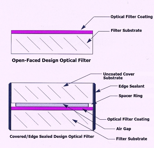
Open-Faced
|
Open-Faced
|
Open-Faced & Covered/Sealed
|
VUV to UV TRANSMISSION MEASUREMENTS
eSource Optics supplies individual Transmission Calibration curves in the VUV to UV ~120nm - 320nm wavelength region with each Optical Filter we supply. All eSource Optics VUV to UV Optical Filters are measured on a Vacuum Spectrophotometer system capable of measuring VUV through UV Transmission as short as 120nm. The system is based on a calibrated Model VM-502 0.2 Meter Vacuum Monochromator with VUV enhanced 1200g/mm grating & Deuterium light source for very accurate VUV to UV wavelength measurements.
TEMPERATURE EFFECT ON VUV to UV OPTICAL FILTERS
· Peak Wavelength Shift: Approximately 0.1 Angstrom / 1°C
· Maximum Temperature: Not to exceed 100°C
· Minimum Temperature: Range to a low of -20°C
· Maximum Temperature Change: Rate of increase or decrease should not exceed 25°C / hour
VUV to UV OPTICAL FILTERS HANDLING AND CLEANING INFORMATION
· Handling and Usage of VUV to UV Optical Filters*: eSource Optics Metal-Dielectric-Metal (MDM) thin-film VUV to UV Optical Bandpass Filters are enivronmentally stable in most low humidity Laboratory type environments, or when used in vacuum or highly purged instrumentation. However, due to the relatively soft nature of the MDM filter coating, care must be taken to avoid damage from contamination of the optical surfaces as these coatings are really not suited for any chemical cleaning or exposure to certain environments; such as ozone or corrosive gases. Also, typically in most all vacuum applications there no epoxies or glue used to hold the VUV to UV Optical Filter; or paints/sealants to blacken the filter edges because most all of these materials will out-gas under vacuum and leave a residue on the surfaces of the filter and contaminate the environment within a vacuum chamber. VUV to UV Optical Filters are typically mechanically mounted using stainless steel or aluminum retaining or split rings to hold the Optical Filter into a mount. If the Filter is to be used in a vacuum application, the normal ozone and other contamination processes which take place in VUV instrumentation can be minimized by not allowing the UV light source or other radiation to strike the MDM Optical Filter coating until the vacuum system is under a 10-5 Torr or below range (never above 10-4 Torr range). Caution should be exercised to avoid accidental high pressures within the vacuum chamber during UV light source operation. As deterioration of MDM filter coatings is a function of photon energy, flux density and time; VUV to UV light sources should only be run when necessary to obtain data. As VUV to UV Optical Filters are MDM type filters and out-of-band blocking is primarily due to reflection/absorption of unwanted light, the coated MDM surface should be oriented towards the light source. In reality the VUV to UV Optical Filter will perform if oriented either way, but it helps somewhat to have the coated "most reflective looking" side facing the incident VUV to UV light source in order to help reduce any thermal load on the VUV to UV Optical Filter. Due to the higher absorption of VUV to UV Filter coating materials; distance to the light source also is very important. The closer the VUV to UV Optical Filter is to a high intensity VUV to UV light source, the faster it can degrade over time. Conditions such as vacuum pressure and cleanliness of the vacuum or purged environment can all play a part in ultimate VUV to UV Optical Filter life-times.
(*Note: The above information is also applicable to eSource Optics VUV-UV Mirrors & Beamsplitters)
· Cleaning of Open-Faced Optical Filters*: Clean dust or other small particles by blowing off the coated surface with a clean air syringe or preferably with purified dry N2. DO NOT contact the coated surface of the filter with any liquid solvents or lens tissue. Typical particle cleaning can be accomplished by the use of a stream of dry air, however surface stains and oil based fingerprints are extremely difficult to remove without damaging the coating. The recommended cleaning of a VUV-UV Filter is with high purity dry nitrogen dispensed with a filtered ionized air gun to remove any dust particles that may cling to the coated MDM surface due to a static charge. We do not recommend that the Optical Filters MDM coated surface be touched with any solvent cleaning methods; or any commercially available nitrogen air spray cans, as these tend to "spit" liquid and will stain the coated surface.
(*Note: The above information is also applicable to eSource Optics VUV-UV Mirrors & Beamsplitters)
· Cleaning of Covered & Edge Sealed Optical Filters: Clean small particles by blowing off the coated surface with a clean air syringe. If needed, use Isoproply Alcohol and a soft, lint-free lens tissue in a drag-wipe motion to remove surface stains. Difficult stains such as oil-based finger-prints typically can be removed with Acetone and a soft, lint-free lens tissue in a drag-wipe motion.
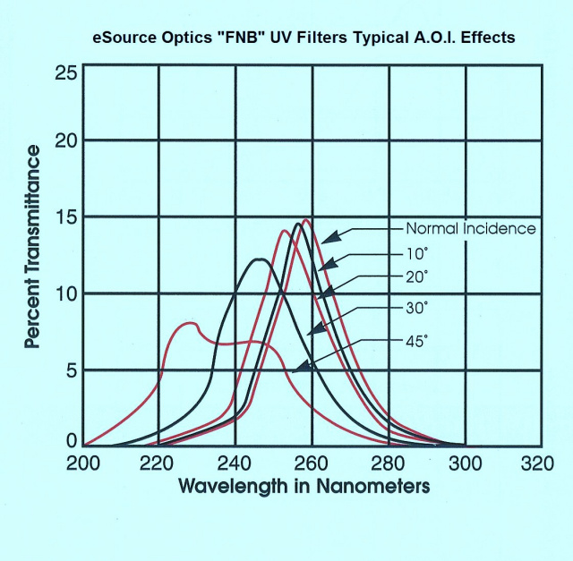
VUV to UV Narrowband Filter Typical ANGLE OF INCIDENCE (A.O.I.) Effects
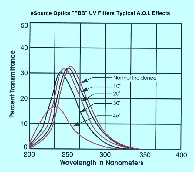
VUV to UV Broadband Filter Typical ANGLE OF INCIDENCE (A.O.I.) Effects
Contact us with any questions